DIY Newtonian Reflector Telescope
02/17/24
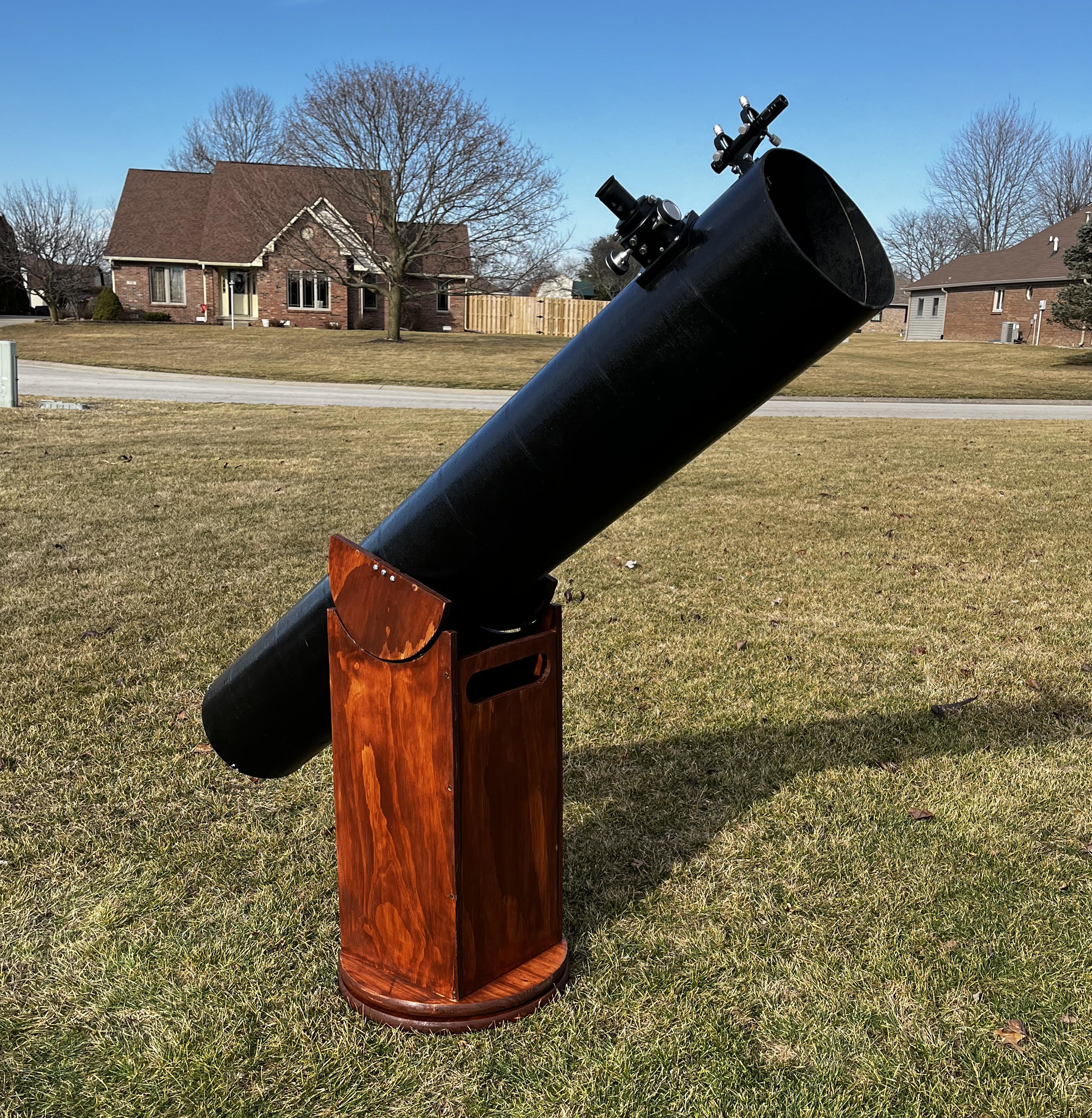
Over the past couple of months, I designed and built a Newtonian reflector telescope. I greatly enjoyed the experience of building this telescope and seeing it function as expected in the end.
I. Background and theory
The main types of telescope designs are the reflector, refractor, and catadioptric. Simply put, reflectors use mirrors to focus a distant image, refractors use lenses, and catadioptric systems use a combination of mirrors and lenses. I decided to build a reflector because it looked like the most feasible design to build. There is also a large online community of DIY reflector enthusiasts, and I figured I'd be able to find advice from this body of public knowledge.
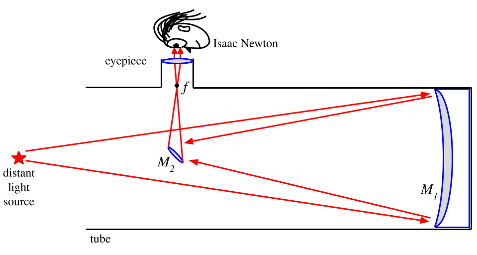
Isaac Newton allegedly invented the most popular reflector telescope design. The optics consist of a large concave mirror at the bottom of the telescope tube (primary mirror, $M_1$) and a smaller 45 degree offset mirror (secondary mirror, $M_2$) near the other end of the tube. The primary mirror collects the light that comes into the opening of the tube and reflects it onto the secondary mirror, which is offset at 45$^{\circ}$ from the optical axis (imaginary line going through the center of tube). The secondary mirror then reflects the light into a focuser tube which contains the eyepiece (a lens or system of lenses) which then outputs the light into the observer's eye.
The diagram below displays the path of the reflected light in the telescope. It's a simple system, in theory. A tube, two mirrors, and an eyepiece. That's the whole thing. The ultimate purpose of every stage of this scope's construction is to physically place the optical components in their appropriate positions in order to create and focus a magnified image of a distant object for an observer (Isaac Newton, in this case) to view.
Primary mirror, $M_1$
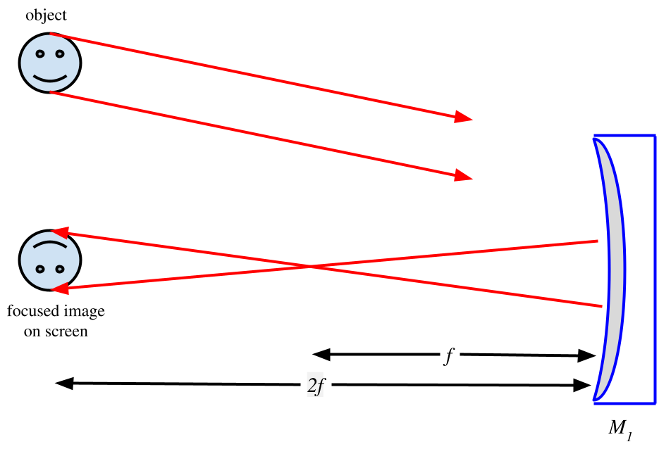
The purpose of the concave primary mirror is to collect light and focus it at a point (see Figure 2). I purchased this mirror set on Amazon for $120.
The optical power of a reflector telescope is typically quantified by its primary mirror's diameter, $D$, and focal length, $f$. The quantity $N = \frac{f}{D}$ is often referred to as the f-number, f-ratio, f-stop, or focal ratio (note that what I call $N$ is also frequently referred to as #). I'll stick with f-number for the rest of this writeup. The convention is to label the mirror by its aperture, $\frac{f}{N}$. The primary mirror I purchased is specified with $D=203$ mm and $f=1600$ mm. So, $$\begin{eqnarray} N &=& \frac{1600}{203} \\ &\approx& 8 \end{eqnarray}$$ This gives an aperture of $\frac{f}{8}$.
If unknown, the focal length of a concave mirror can be found by reflecting light off of it onto a screen. The distance at which the image on the screen comes into focus is $2f$.
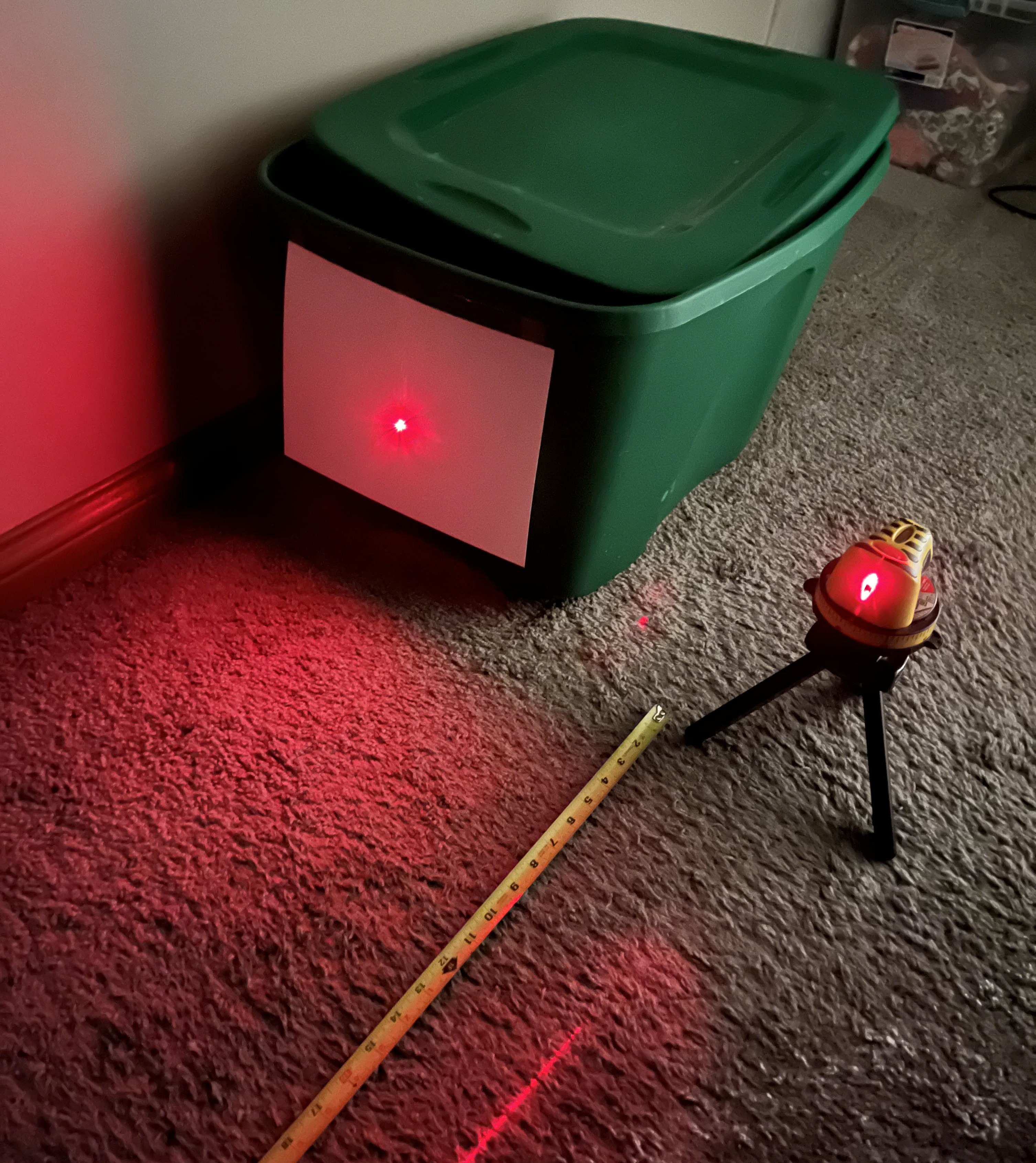
I checked my primary mirror's focal length with a laser level. I measured the point of focus to be about 3.2 m away from the mirror. This gives a focal length of 1.6 m, i.e. the labeled focal length.

A mirror with a larger diameter has more surface area to capture light, which gives better captured images (remember: a circle's area is proportional to its radius squared). For this reason, primary mirrors with smaller values of $N$ are said to be "faster" than mirrors with larger $N$. Faster mirrors also cost many more dollars.
The actual quality of the mirror itself is often denoted by a measure of its flatness called the peak-valley ratio (P-V). This ratio tells you how much deviation you can expect in the reflected light's waveform as a fraction of the light's wavelength. Given that I cheaped out on an Amazon mirror of dubious optical quality and that I don't have any high-quality interferometry equipment, I don't know what the P-V ratio of my mirror is.
Secondary mirror, $M_2$
The secondary mirror has an elliptical shape and sits on a 45$^{\circ}$ angle. After reading around a bit on various telescope forums and guides, most people suggest a secondary mirror with a minor axis in the range $[0.15, 0.25]$ of the diameter of the primary mirror. Secondary mirrors smaller than this don't reflect a large enough image, and mirrors larger than this block the amount of light that the primary mirror can collect. The mirror set I purchased came with a 40 mm secondary, which is ~0.19 times the diameter of the primary.
The entire optical system
The magnification of the telescope is given by $M = \frac{f}{f_e}$ where $f=$ focal length of the primary mirror and $f_e=$ focal length of the eyepiece. I started with a 10 mm and 26 mm eyepiece. With my primary mirror focal length of 1600 mm, this gives me the options of 160x or 61.5x magnification. This range of magnification is good enough to observe the moon, planets in our solar system, and deep sky objects.
$M_1$ sits at the bottom of the tube on top of a mount. That's easy. But where does $M_2$ sit? And, correspondingly, where does the focuser hole go? The position of $M_2$ relative to the bottom of the tube depends on a few parameters outlined in the diagram below.
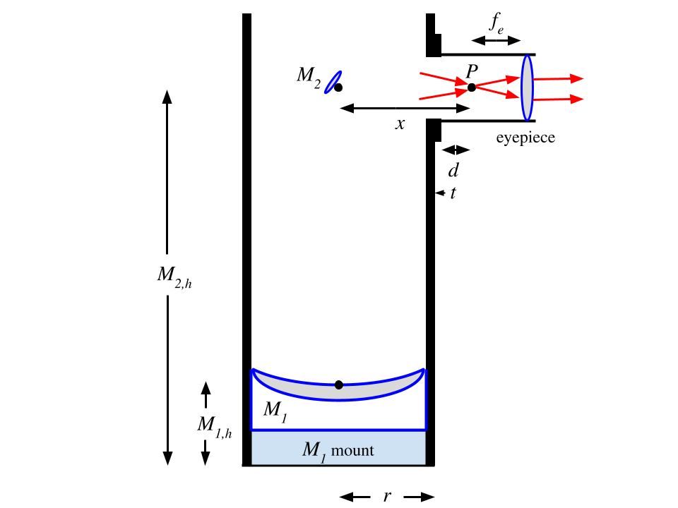
The parameters in this diagram are defined as:
$M_{1,h}$: distance from bottom of tube to center of $M_1$ (includes mount)
$M_{2,h}$: distance from bottom of tube to center of $M_2$
$r$: outer radius of tube
$t$: thickness of focuser bottom
$P$: reflected focal point (plane where $M_1$ reflection focuses)
$d$: distance from bottom of focuser tube to $P$
$f_e$: focal length of eyepiece
$x$: distance from $M_2$ to $P$
We want to find $M_{2,h}$ so that we know where to position $M_2$ and where to drill the focuser hole. By definition, the distance from the mid-point of $M_1$ to the focal plane is the focal length of $M_1$, $f$. Meaning, $$\begin{eqnarray} f = M_{2,h} - M_{1,h} + x \end{eqnarray}$$ So, $$\begin{eqnarray} M_{2,h} = f - x + M_{1,h} \end{eqnarray}$$ Great. We know $f$ and can find $M_{1,h}$ by measuring the thickness of the mirror and its mount. What is $x$? Well, $$\begin{eqnarray} x = r + t + d \end{eqnarray}$$ We can measure the values of $r$ and $t$. But what is $d$?
Once $M_2$ is positioned, $P$ is fixed at a point in the focuser tube. The focuser allows for movement of the eyepiece closer to or farther from $P$. This adjustment is made to bring the magnified image into focus when looking into the eyepiece (i.e. set the distance between $P$ and the eyepiece to $f_e$). The focal length of the eyepiece, $f_e$, is a fixed value for each eyepiece used. So, $d$ is the only variable once all components are put in place. Focusers have a maximum distance they can be adjusted in and out. Based on the focuser's movement limitations and the focal lengths of the eyepieces you intend to use, the value of $d$ can be determined empirically. Ideally, you should set $d$ so that you can bring your smallest focal length and longest focal length eyepieces into focus.
With the limitations of my focuser, I determined that $d$ should be about 8.5 cm in order to focus images using eyepieces with focal lengths in the range 5 mm to 35 mm. This covers the practical range of eyepiece focal lengths used in the average backyard Newtonian experience, and my focuser's tube has a length that is probably close to most other commercial focusers.
Okay, so now we have a value for $d$. Let's substitute the equation for $x$ into the $M_{2,h}$ equation: $$\begin{eqnarray} M_{2,h} = f - r - t - d + M_{1,h} \end{eqnarray}$$
All values in the above equation are known and we can now calculate the position of $M_2$ from the bottom of the tube. This is also the position where the center of the focuser hole should be drilled. For my components I measured/determined the following values:
$f=160$ cm
$r=13.14$ cm
$t=0.6$ cm
$d=8.5$ cm
These values are all approximate measurements, but they're close enough (I propagated measurement errors and decided that the final delta on $M_{2,h}$ was negligible considering that I can't drill a straight hole in an exact position anyways). This gives a final value of: $$\begin{eqnarray} M_{2,h} = 144.75 \text{ cm} \end{eqnarray}$$
I'm an American who doesn't have an intuitive feel for the metric system nor a metric tape measure, so I'll call this:
$$\begin{eqnarray} M_{2,h} = 57 \text{"} \end{eqnarray}$$Motion and position of the telescope
Given a latitude and longitude position on Earth, the position of every visible celestial object can be calculated. Celestial positions can be defined by azimuth and altitude angles (az/alt). It is also common to see positions defined on the celestial sphere, which gives right ascension and declination angles (RA/Dec). I find it easier to think in the az/alt coordinate system, so that's what I'll continue with. I haven't read about the methods to calculate celestial positions yet, and it's not necessary if you don't want to. There are several applications that provide you with the positions of celestial objects relative to your position on Earth. I use the mobile version of Stellarium.
Once you have the az/alt angles of a celestial object relative to your latitude and longitude position, you simply point the telescope to those angles, and ideally you will see a magnified image of the object.
II. The build
Tube
Concrete form tubes are a common choice for DIY Newtonians. They are rigid and good at protecting against moisture (ya know, they're meant for pouring wet concrete). Maybe just as important is that they're cheap and easy to drill into.
The tube needs an inner diameter a bit larger than the diameter of the primary mirror. For my 8" primary mirror, this meant a tube with a 10" inner diameter. As described above, the length of the tube is dependent upon the focal length of the primary mirror, its diameter, and its position. For my 1600 mm focal length mirror, this meant purchasing a bit over 6 feet of tube and cutting it down to 57" (I used the extra tube to test cuts on). I purchased this tube from a local building supply retailer.
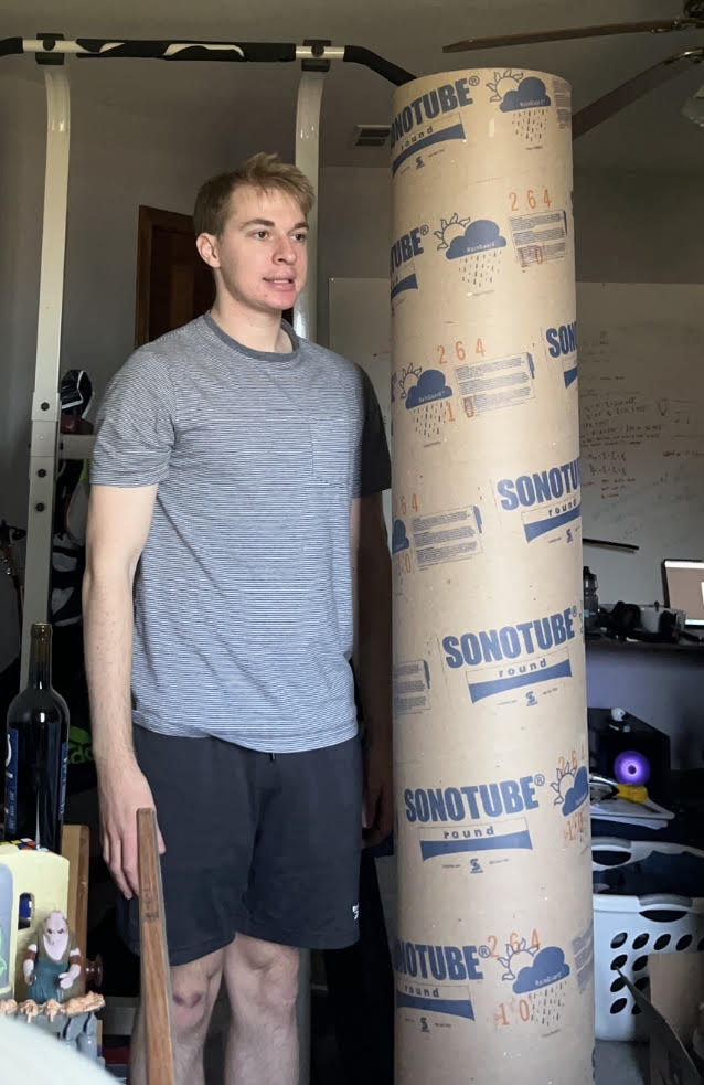
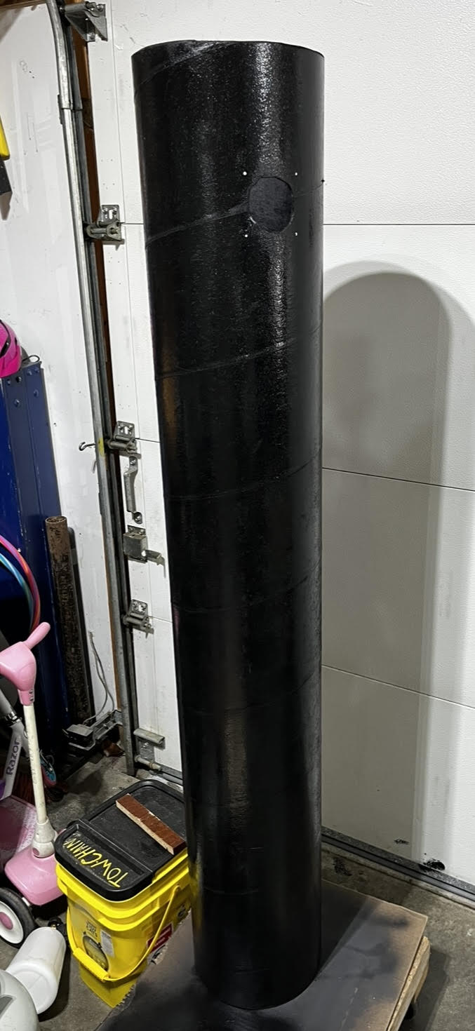
For extra moisture protection, longevity and aesthetics, I spray painted the outside of the tube with a couple coats of primer and a couple coats of black paint. I followed this with some light sanding (1000 grit) to smooth the surface. I also rolled black paint onto the inside of the tube (and painted my arm black in the process).
Primary mirror mount
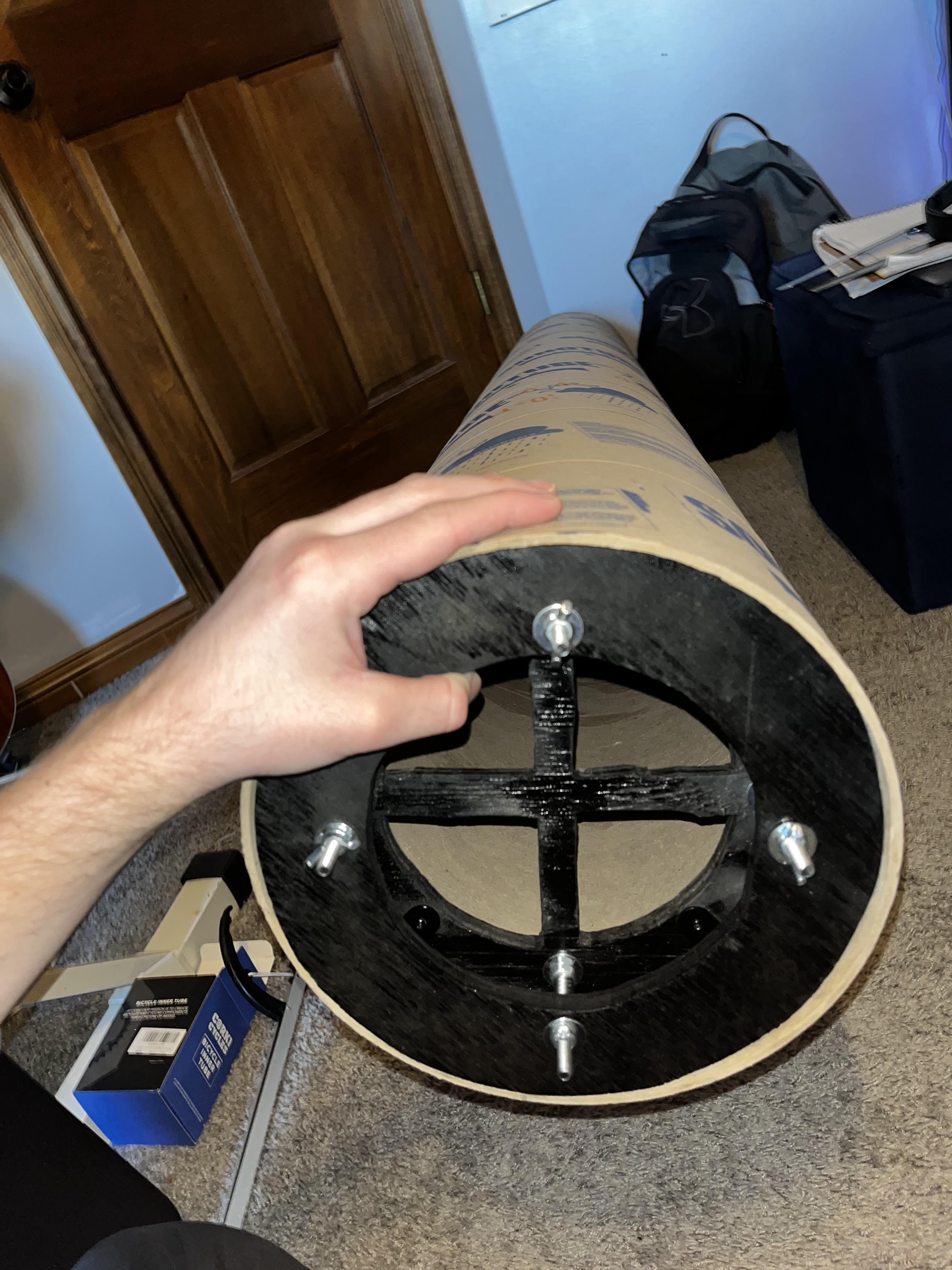
Figure 2 makes mirror mounting look deceptively simple. Just put the primary mirror at the bottom of the tube. But how? It won't just stick there. You need to build a mount. And that mount needs to allow for collimation adjustments (more on this later).
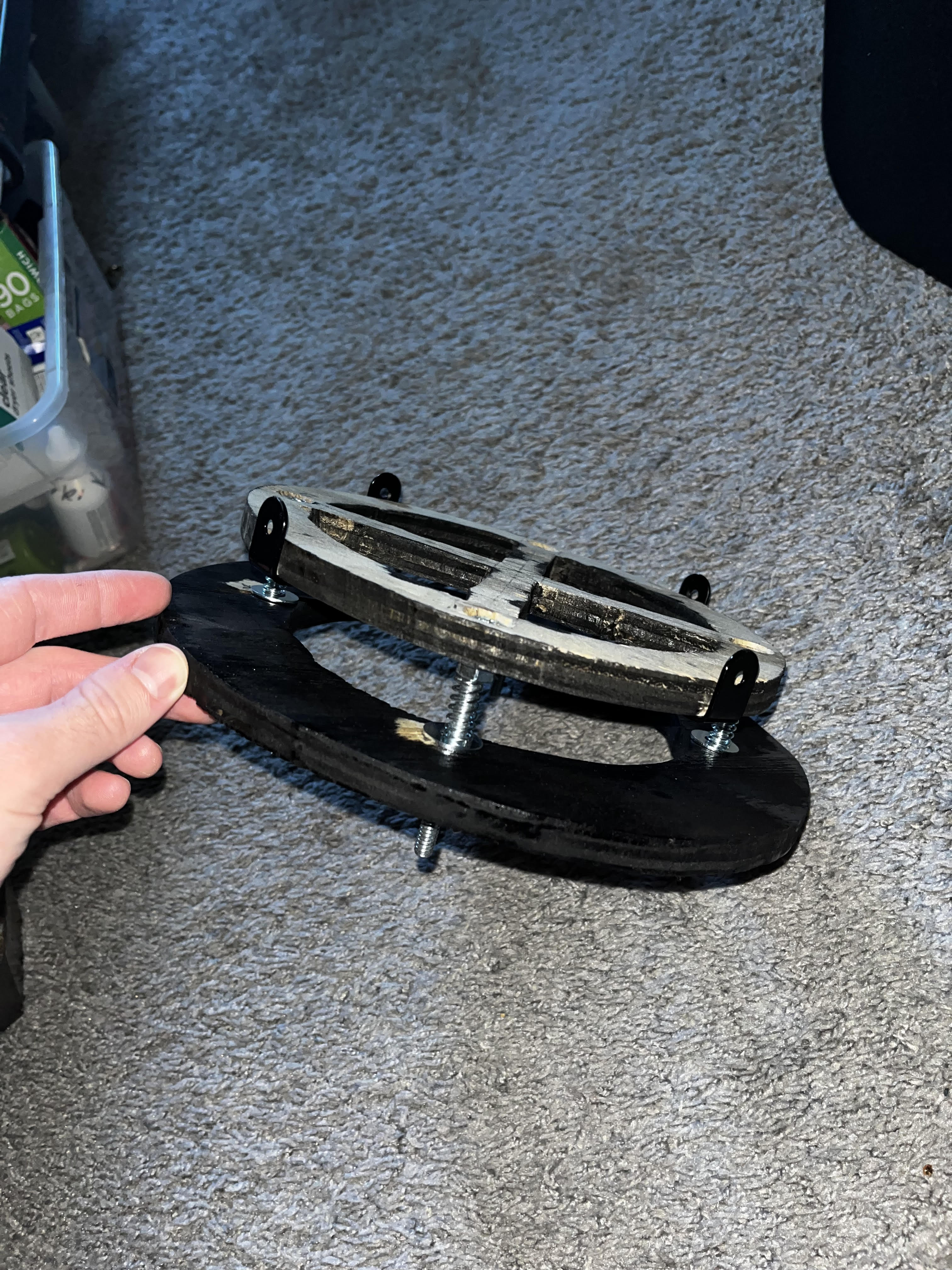
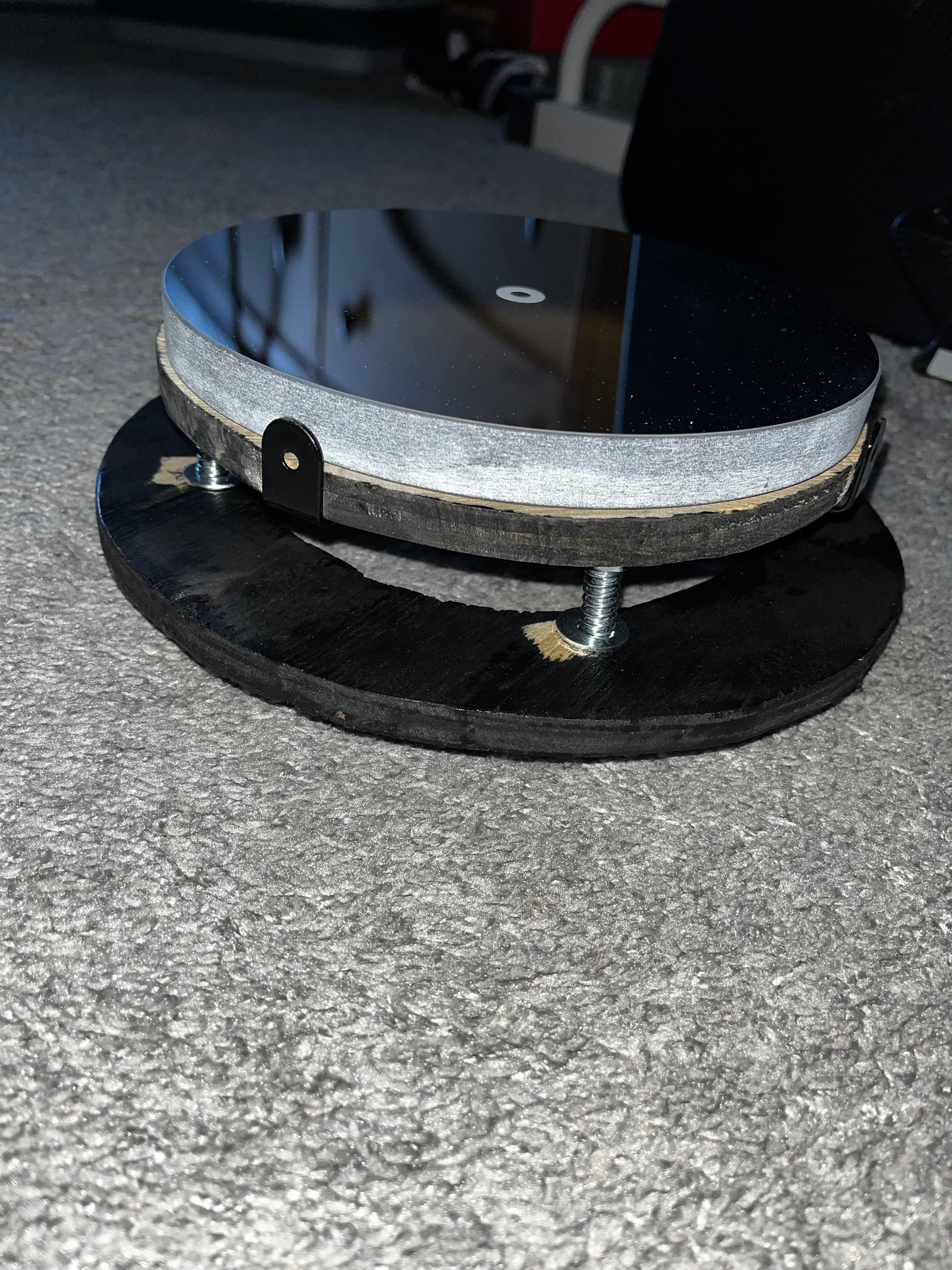
I decided to make the mount out of wood. I roughly followed the design described by Gary Seronik (there are a ton of other useful astro DIY explanations on his site too). The design consists of a wooden plate (mirror plate) for the mirror to sit on and a larger plate (base plate) that screws into the tube itself. Before cutting out the plates, I cut holes in the middle of each plate for better heat dissipation. I'm not sure how important this really is, but I did it. All cuts were made with a jigsaw.
I drilled four countersunk holes into the top of the mirror plate. Four concentric holes were drilled into the base plate. Four 3" 1/4"-20 countersunk bolts were then placed into the holes. Four hex nuts (with washers) were tightened onto the bolts to secure them to the mirror plate. Springs were placed over the long ends of the bolts. Washers were placed between the top of the base plate and the bottom of each spring. Four wingnuts (with washers) were threaded onto the bolts on the bottom side of the base plate. By tightening/loosening these wingnuts, the springs are compressed/expanded, which changes the angle of $M_1$ (movement needed for collimation). Lastly, I drilled four angle brackets onto the side of the mirror plate. After checking that the mount worked as intended, I spray painted the plates black (excepting the top of the mirror plate, as $M_1$ covers it).
Finally, I glued the bottom of $M_1$ to the top of the mirror plate and glued the sides to the angle brackets on the mirror plate with silicone RTV adhesive. After 24 hours, $M_1$ became one with its mount. Later in the build, 4 3/8" wood screws were drilled into the outside of the tube and then into the sides of the base plate.
Focuser
The focuser holds the eyepiece and has a turnable knob that moves eyepiece closer to or farther from $M_2$. I purchased this Crayford focuser. I cut out a jagged hole in the tube with a center roughly at the point where the center of $M_2$ is supposed to sit and then bolted the focuser down with some miscellaneous hardware I found in the garage.
Secondary mirror mount
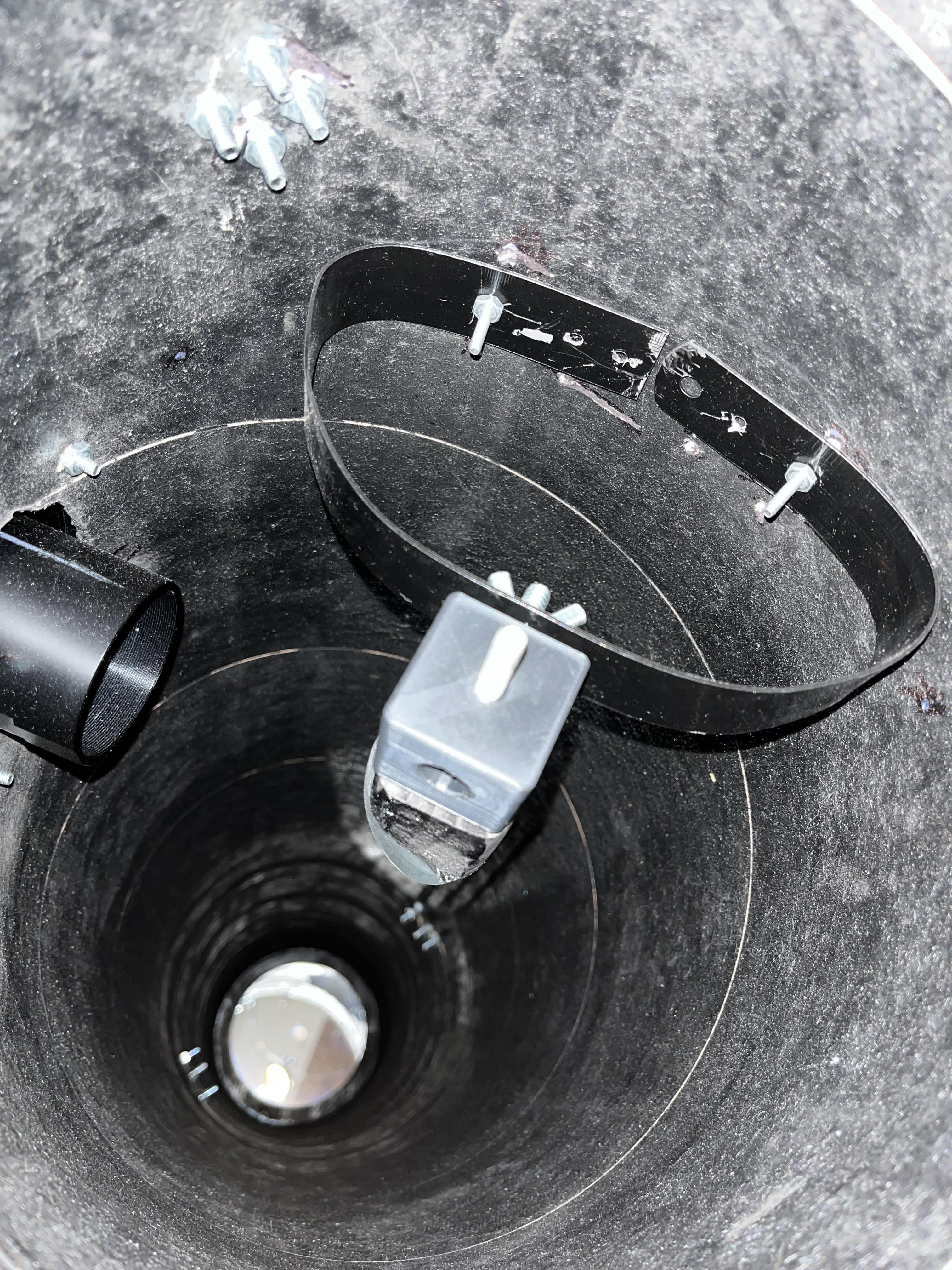
Mounting the secondary mirror was a bit trickier than the primary mirror. The center of $M_2$ must sit along the optical axis going through the center of $M_1$ and be concentric with the focuser hole. It also needs to sit on a tilt of 45$^{\circ}$ relative to the face of $M_1$. To meet these requirements, the secondary mount must allow for $M_2$ to rotate around the optical axis and around the plane parallel to the focal plane. I decided to build a curved vane mount because it looked like it would allow for easy positioning of $M_2$. Again, I mostly followed a design described by Gary Seronik
This mount consists of two blocks, a threaded rod, a machine screw, a 16" stainless steel ruler, and a couple of nuts+washers.
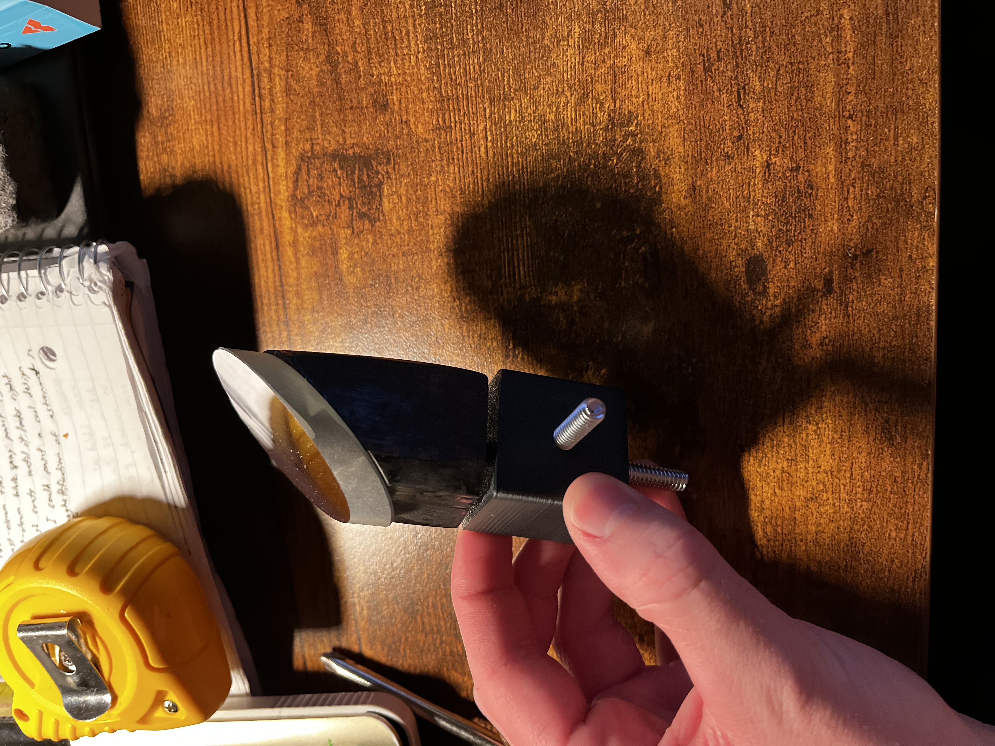
As shown above, the block that the mirror sits on is cut at about 45$^{\circ}$. I found some wooden rods in our garage and cut this piece out with a miter saw and then spray painted it black. The second block is just a cube with a few holes. Initially, I cut this piece out of the same wooden rod, but I split it in half while drilling into it. Fortunately, I have a friend with a 3D printer, and I had him print me out the piece after I modeled it in FreeCAD. The back of $M_2$ was glued to the wooden surface with the same silicone adhesive used for adhering $M_1$ to its mount. A 1/4" hole was drilled through the center of each piece to accept a threaded rod. This rod attaches the pieces together and allows for a rotation along the optical axis once the assembly is placed in the tube. The bolt end sticking out of the side of the cube allows for the rotation along the plane parallel to the focuser plane (i.e. you can adjust this to get the desired 45$^{\circ}$ offset).
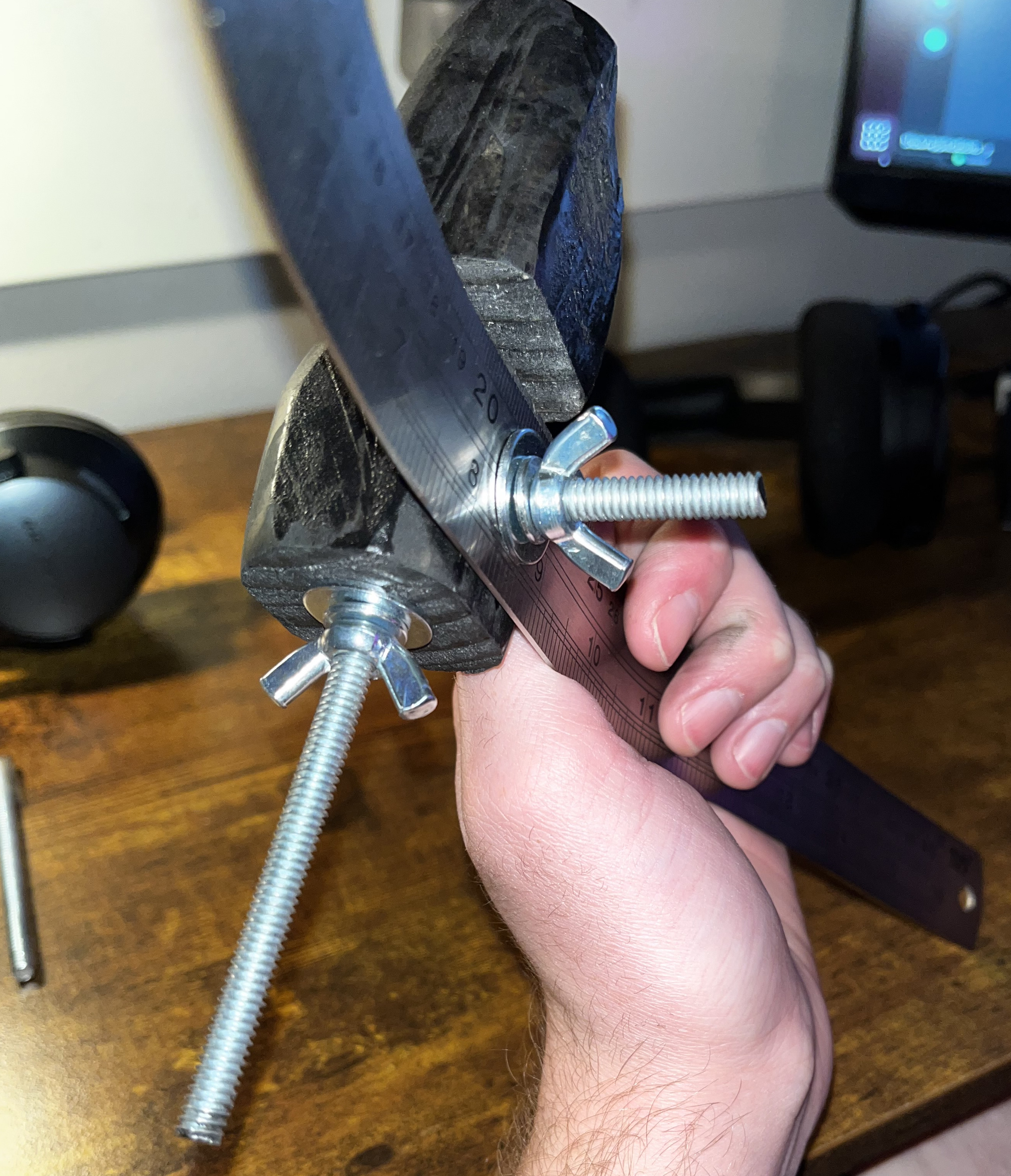
I drilled a hole in the center of the stainless steel ruler and then spray painted it black. The center hole accepts the bolt end sticking out of the cube (note that the above picture has the original wooden cube piece mentioned previously, not the final 3D printed cube). With a bit of hardware, this setup lets you lock the mount's offset angle in place.
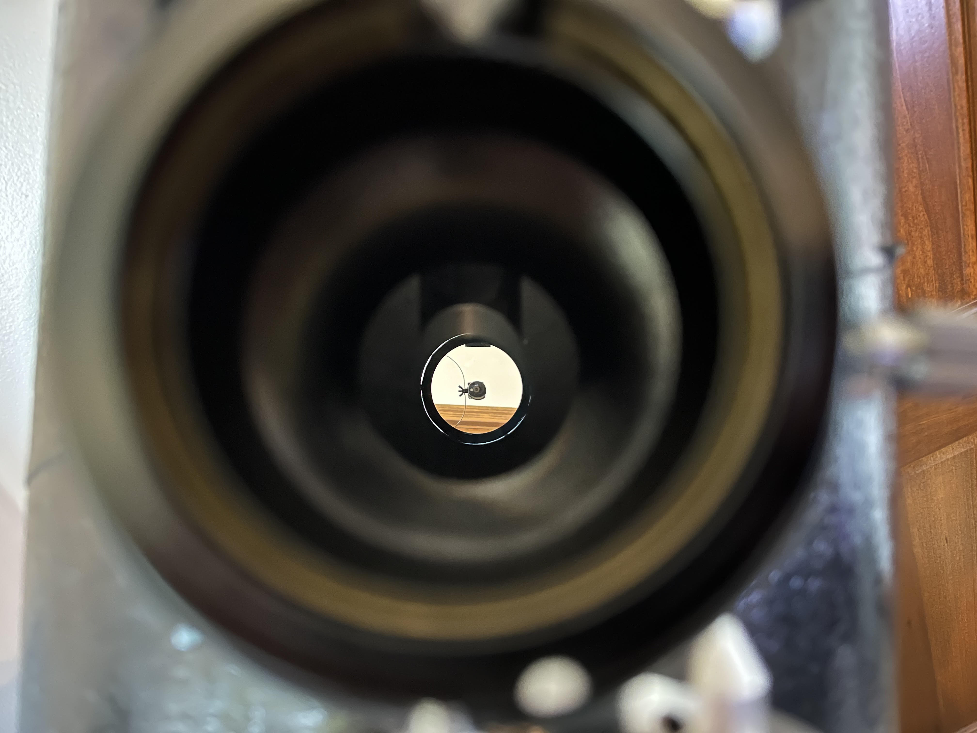
The last step was to mount this entire assembly into the tube. To do this, I drilled holes into both ends of the stainless steel ruler. These holes were made to accept small (maybe 1/8"?) bolts to hold the mount in place. I then flexed and morphed the ruler until it was in a position that put $M_2$ in the center of the tube. This took a lot of trial and error, but I finally got it just right (approximately).
Dobsonian mount
The Dobsonian mount is a common DIY Newtonian mount type. There is no single definition of what a Dobsonian mount is, but generally speaking, the design consists of some sort of azimuth angle-rotating box with two circular altitude-rotating pieces attached to the telescope tube. The mount I built was made entirely with wood.
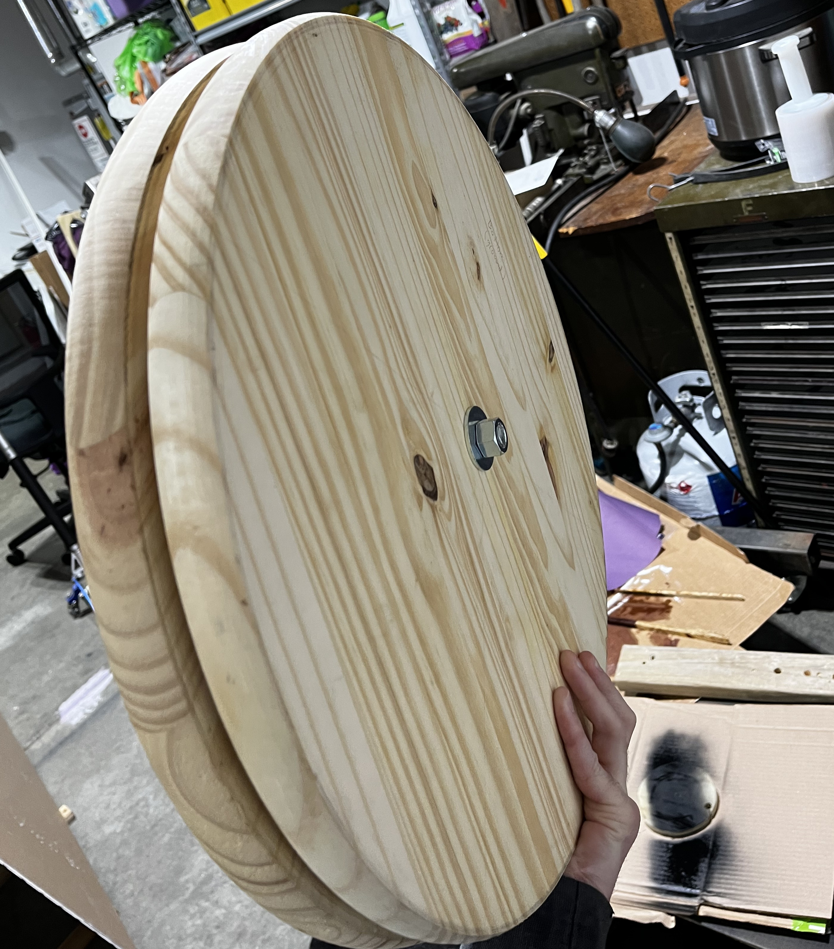
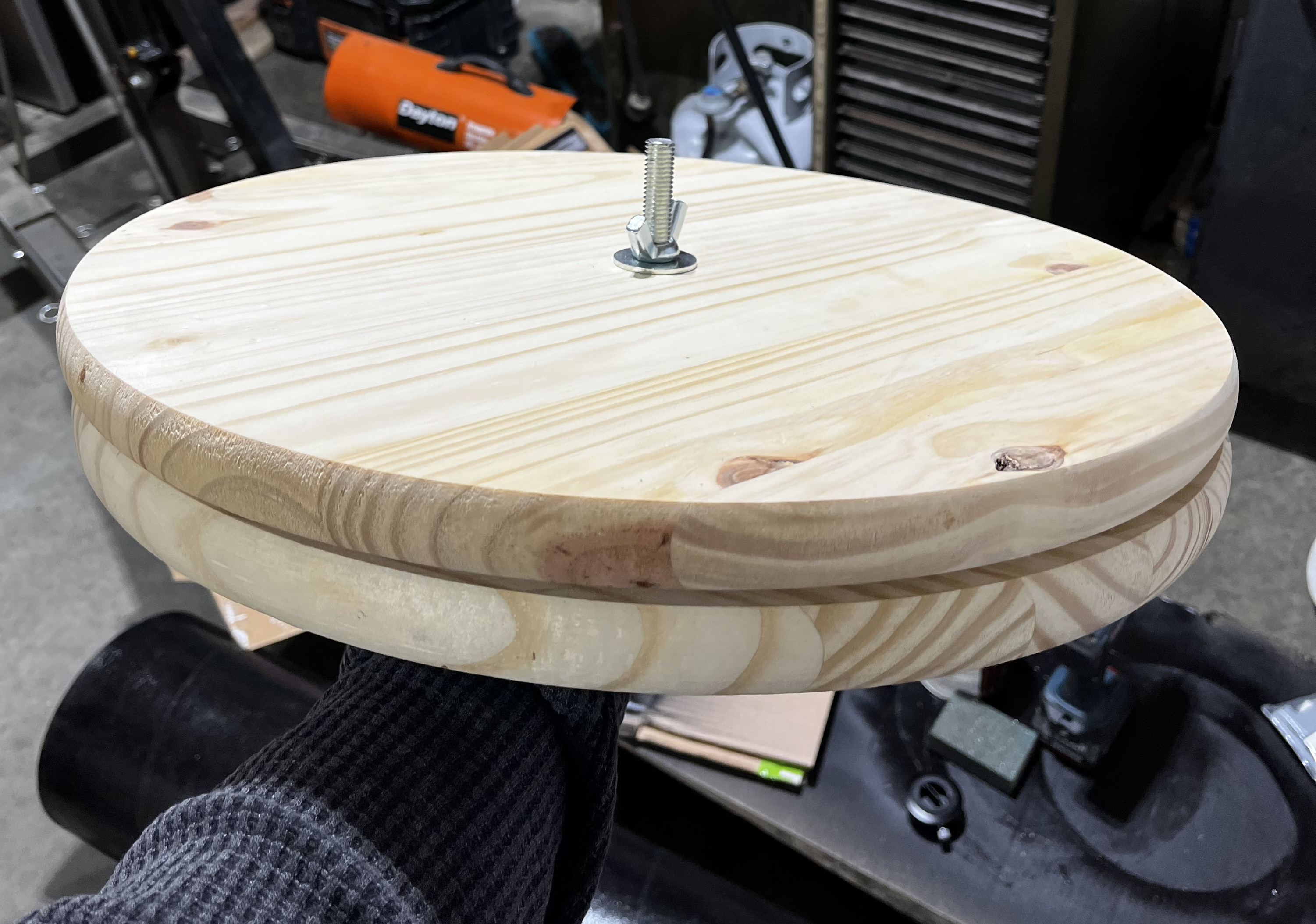
I planned on cutting out two circular plates of plywood for the part of the mount that sits on the ground and rotates around the azimuth, but luckily for me I found pre-cut circular pieces of about the right diameter (~17") at Home Depot. I learned how painful cutting clean circles is with a jigsaw during the creation of the primary mount and did not regret saving myself the effort here. Between these two wooden circles, I screwed in some teflon furniture sliders. These pieces act as the bearings for the azimuth angle adjustment. The friction of teflon surfaces is good for a smooth rotation when you apply enough force, but also enough to hold the scope in place when you don't want to rotate it anymore. I drilled holes in the center of these circles (it took a long time to mark these concentric holes and they're still a little off) and placed a 1/2" threaded rod through them. On the top plate, a wing nut + washer was used to lock the top plate in place, and a hex nut + washer was used to lock the bottom plate in place. I cut out three small rectangular pieces of wood for feet. These pieces were glued onto the bottom of the bottom plate.
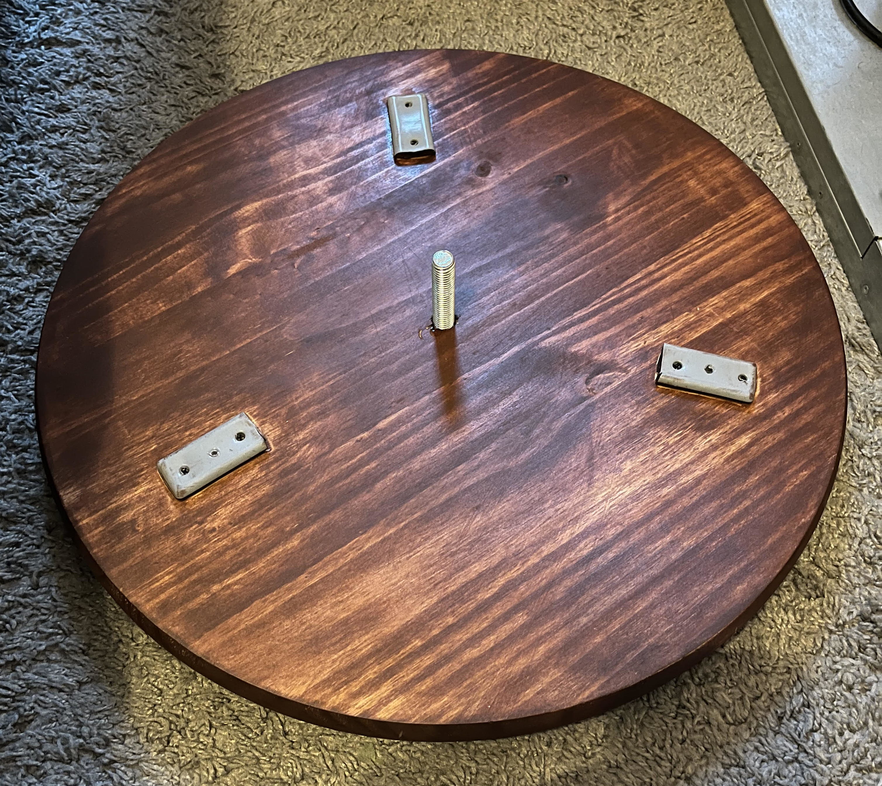
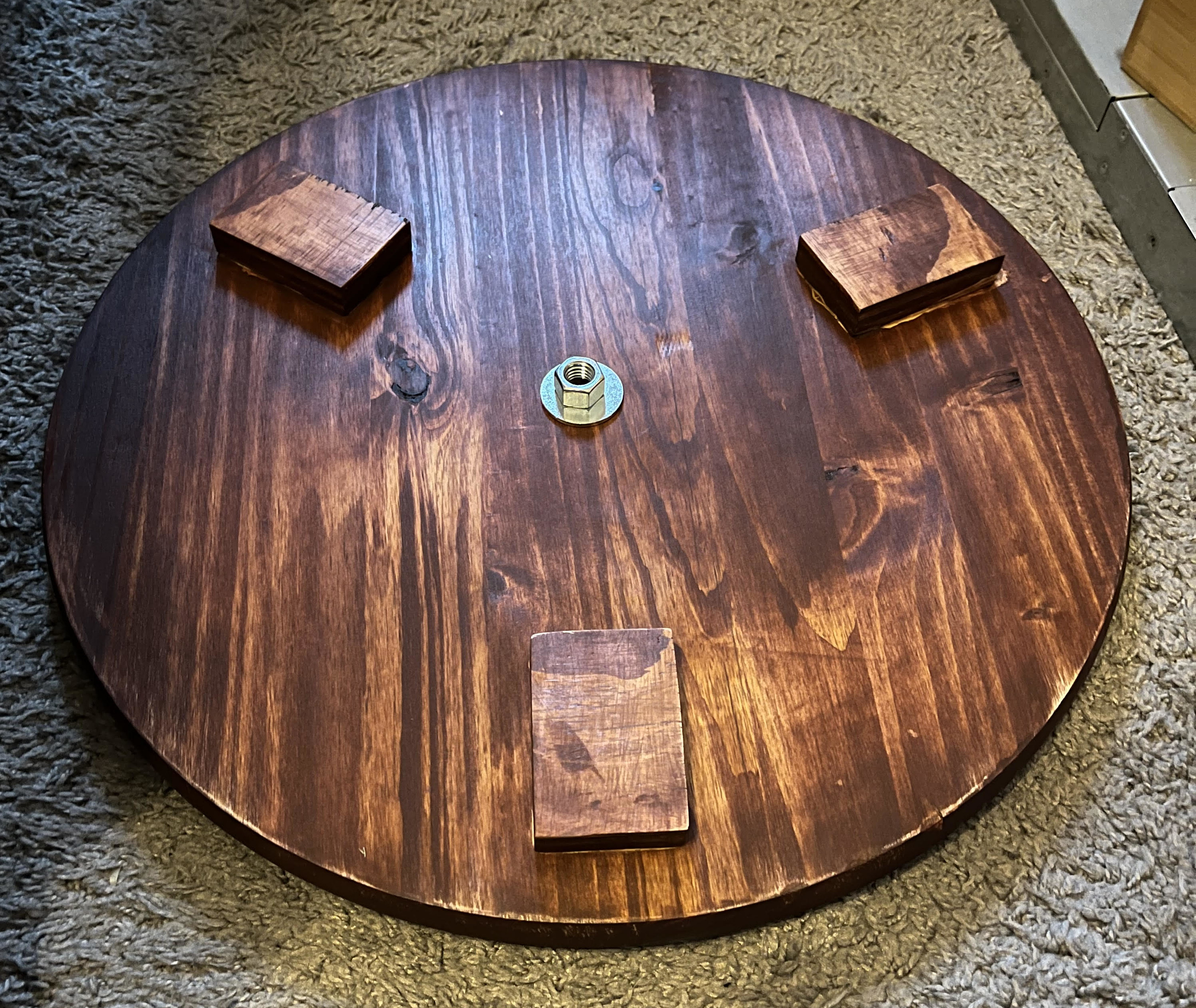
I constructed a three-sided rectangular box (roughly 32"x13"x13") to sit on top of the top azimuth-rotating plate. I cut out the bottom part of a 12" diameter circle on each of the side boards, a handle out of the front-facing board, and two 12" diameter semi-circles to attach the mount to the tube. I then cut off some 2"x1" pieces of teflon and screwed them into the curved part of the side boards. The 12" diameter semi-circles glide along this surface.
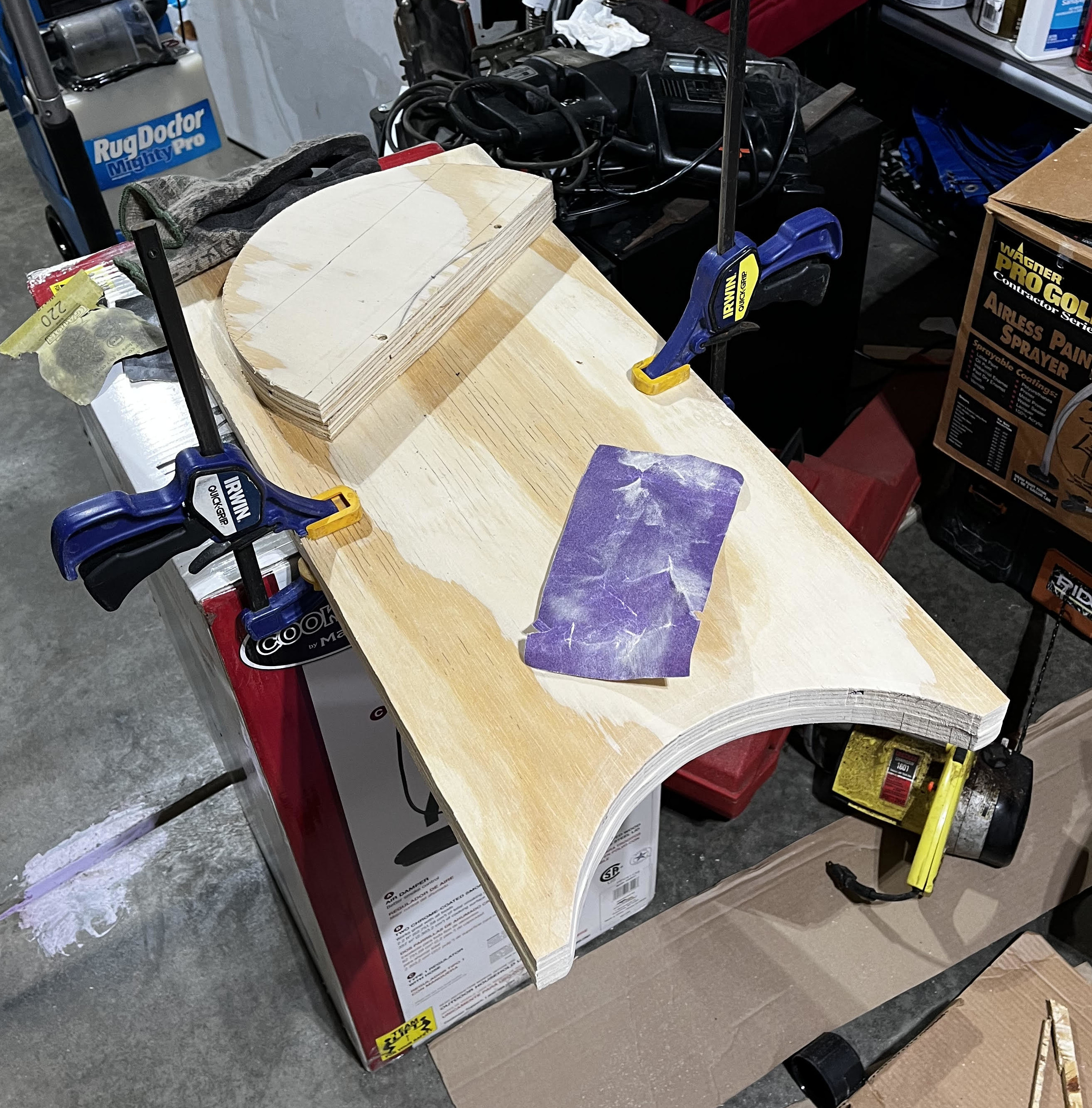
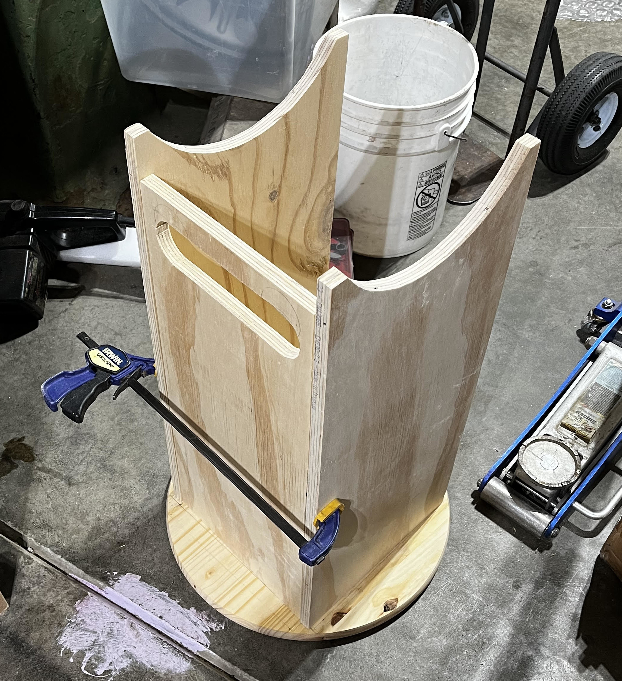
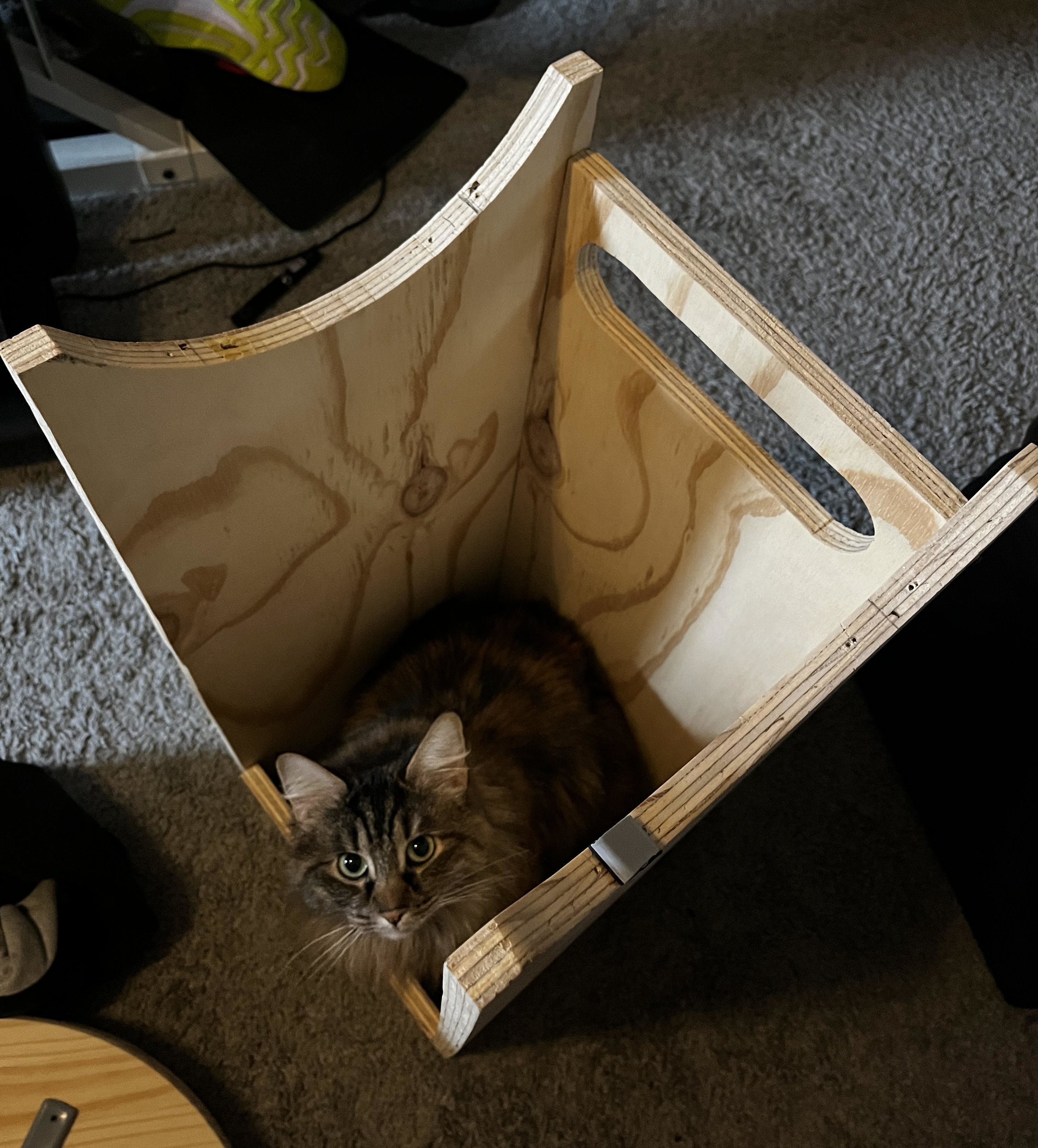
To assemble the box, I screwed the side boards together. I also cut out a 3" wide piece with the length of the front board to keep the side boards from angling in (i.e. to keep the box a box). Finally, I glued the assembled box to the top azimuth plate.
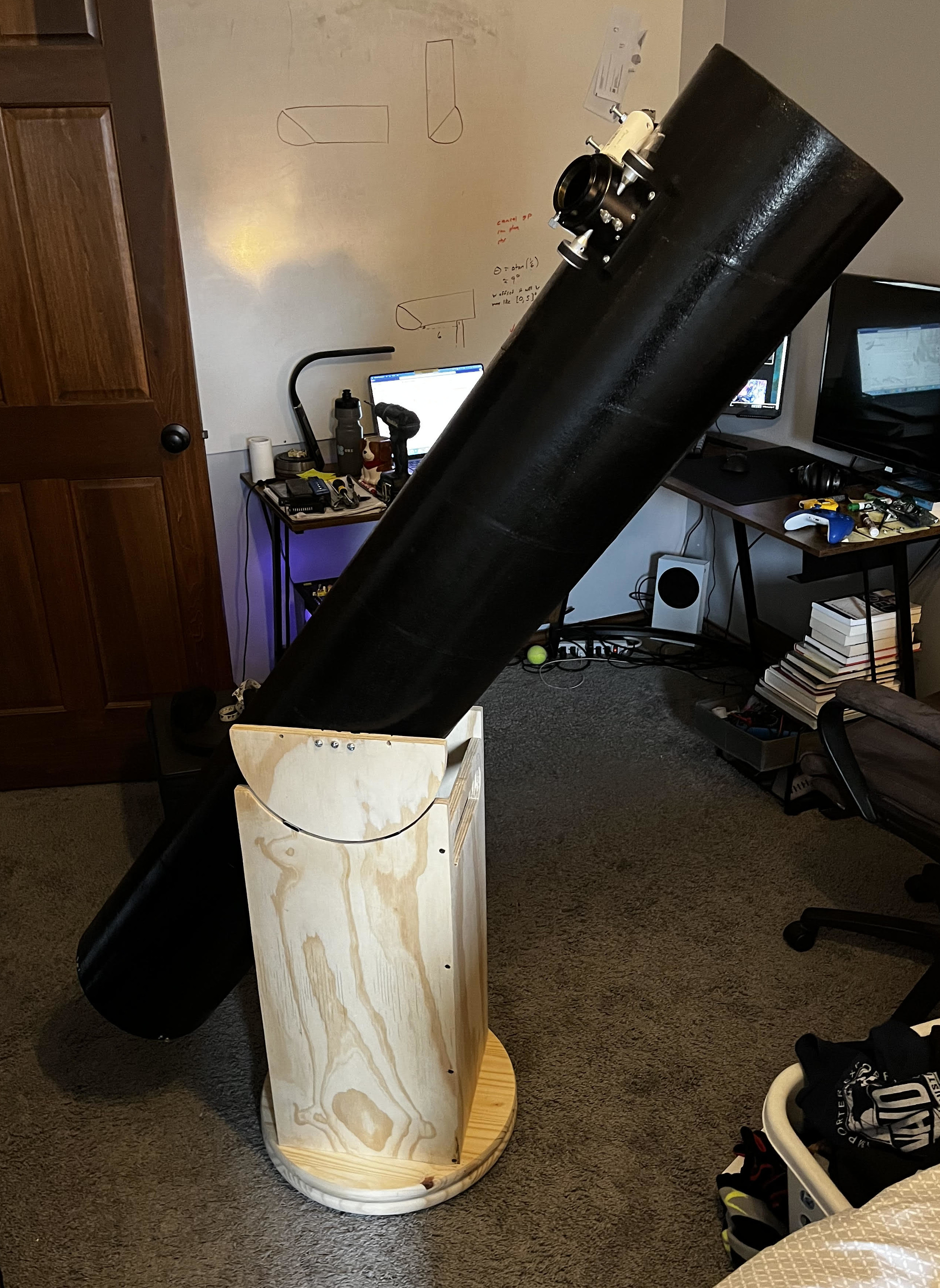
The altitude bearing plates should ideally sit at the balance point of the telescope. I estimated the balanced point to be around 29" up the tube when the heaviest eyepiece is in place. I attached the altitude bearing plates to the tube with 3 bolts each (see image below). At this point, the telescope was functionally complete.
Wood staining
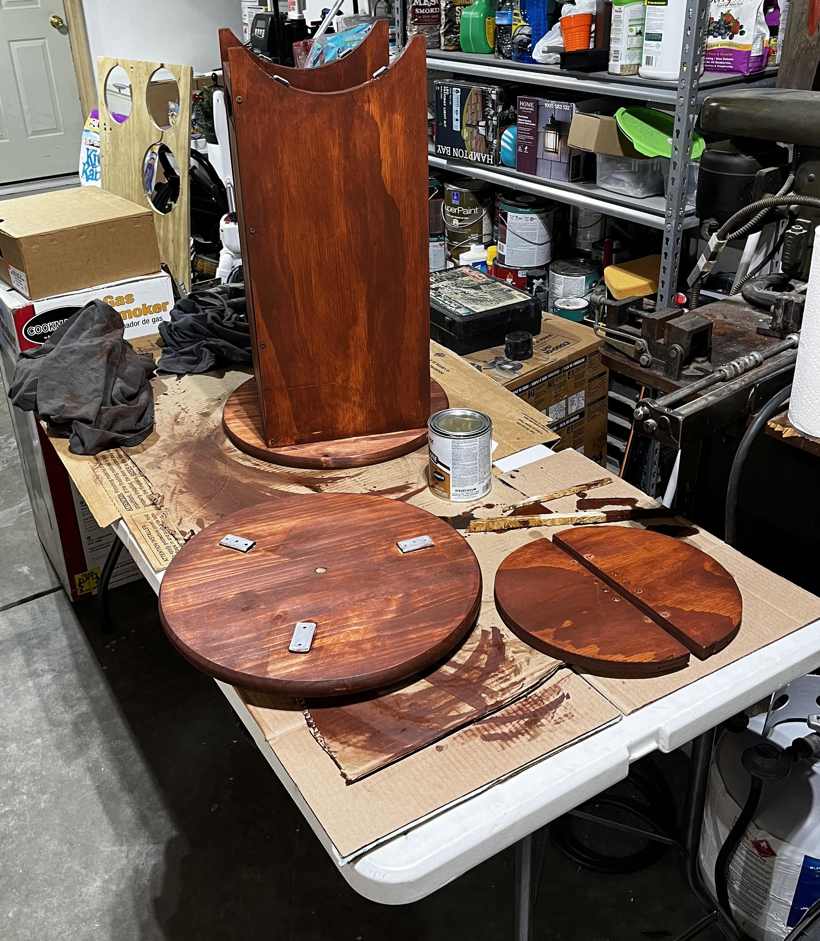
Before assembling any of the wood pieces, I sanded all sides of each piece with 120 and then 150 grit sandpaper. I brushed the pieces off and did my best to remove all remaining wood dust with the leaf blower. This process was quite time-consuming and very tedious, but was worth the effort in order to create a smooth texture and appropriate surfaces for wood stain.
I stained the pieces with the following steps:
- apply pre-stain wood conditioner, wait 30 minutes
- apply stain, wait 8+ hours
- apply polyurethane, wait 8+ hours
- sand pieces with 220 grit (scuff layer)
- apply polyurethane
I used all oil-based solutions and chose the stain color of cognac. I used old t-shirts to apply each layer. This entire process took me a few days to complete and made me pretty light-headed (don't huff paint).
Laser guide
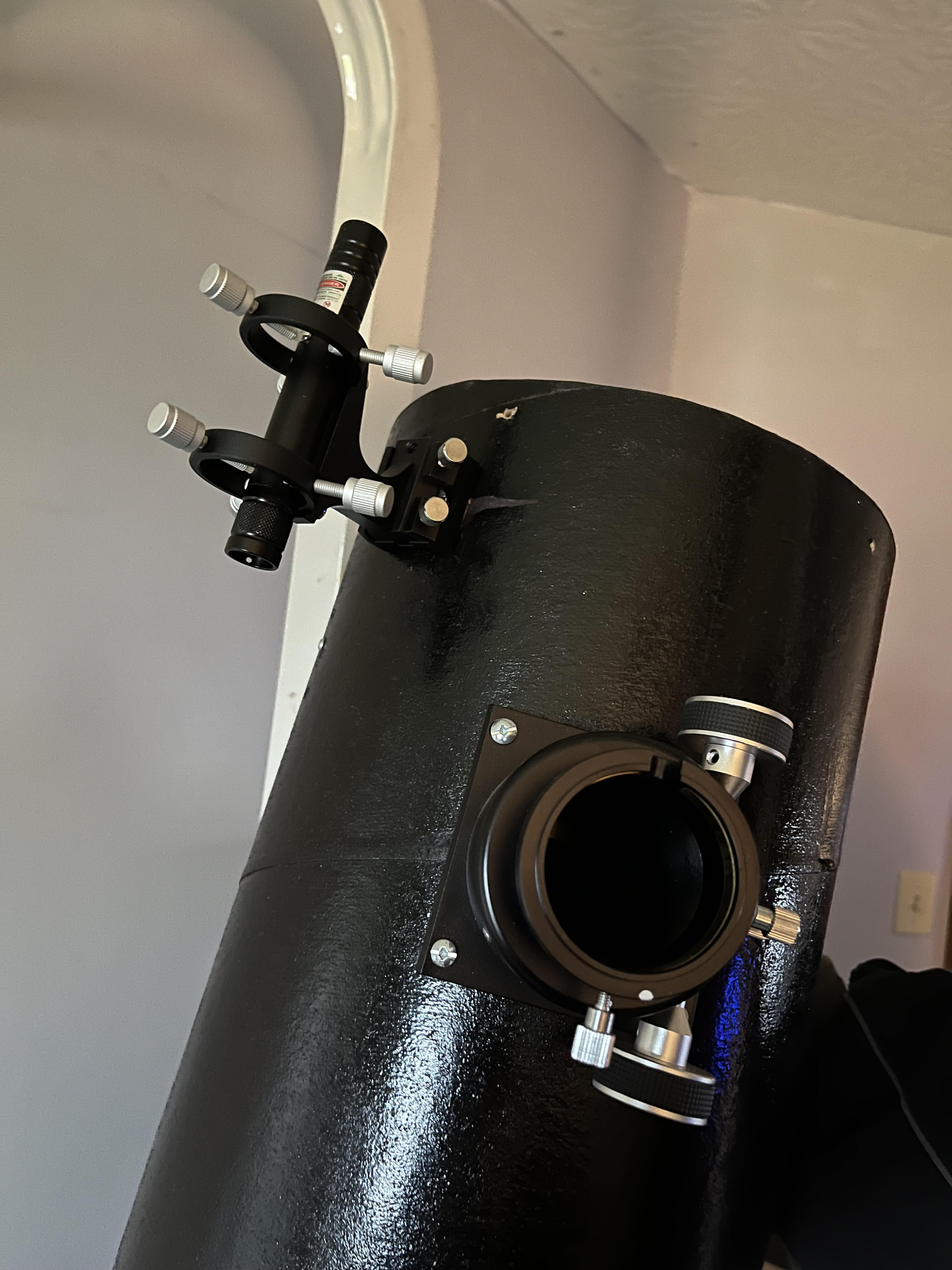
Okay great, the thing is finished. But, how the hell do I point it? Most hand-guided scopes use a finderscope or a laser to aim the tube at a celestial object. I opted for the laser solution because it looked more DIY-able. I purchased this 532 nm (green) laser and attempted to make a mount for it with PVC pipe coupling and spare nuts+bolts.
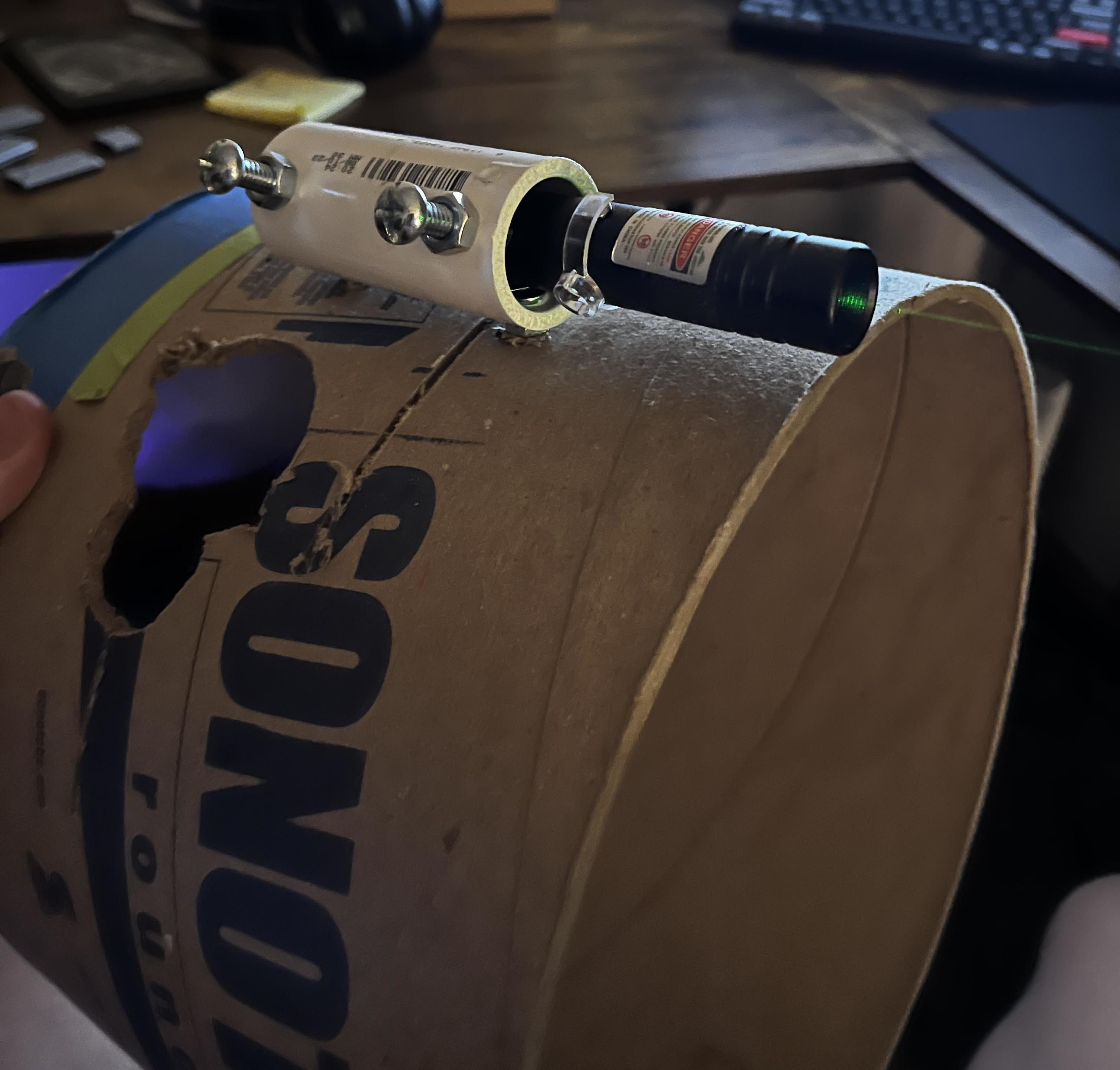
I decided this DIY mount didn't allow for precise-enough adjustments to the laser's position and scrapped this part. At this point I felt a bit mentally drained with the build and I wanted to finish it. That is to say, I caved and bought this laser mount and this mount holder.
Collimation
Collimation is the process of lining up the centers of $M_1$ and $M_2$ with the center of the focuser hole. This is an important alignment step that needs to be completed in order to get good views when looking at objects. Once again, I'll defer to Gary Seronik for a more thorough explanation. When you realize that the goal of collimation is to see concentric circles when you look down the focuser hole, the necessary adjustments become intuitive. I purchased a Cheshire collimator for this adjustment because it looked like less of a hassle to use than a laser collimator. Using the $M_1$ mount angle adjustment hardware described earlier, I simply made the circles concentric.
III. Results
I'm quite happy with the final result. The telescope looks nice and functions as intended. The altitude and azimuth movements aren't the smoothest, but they're good enough.

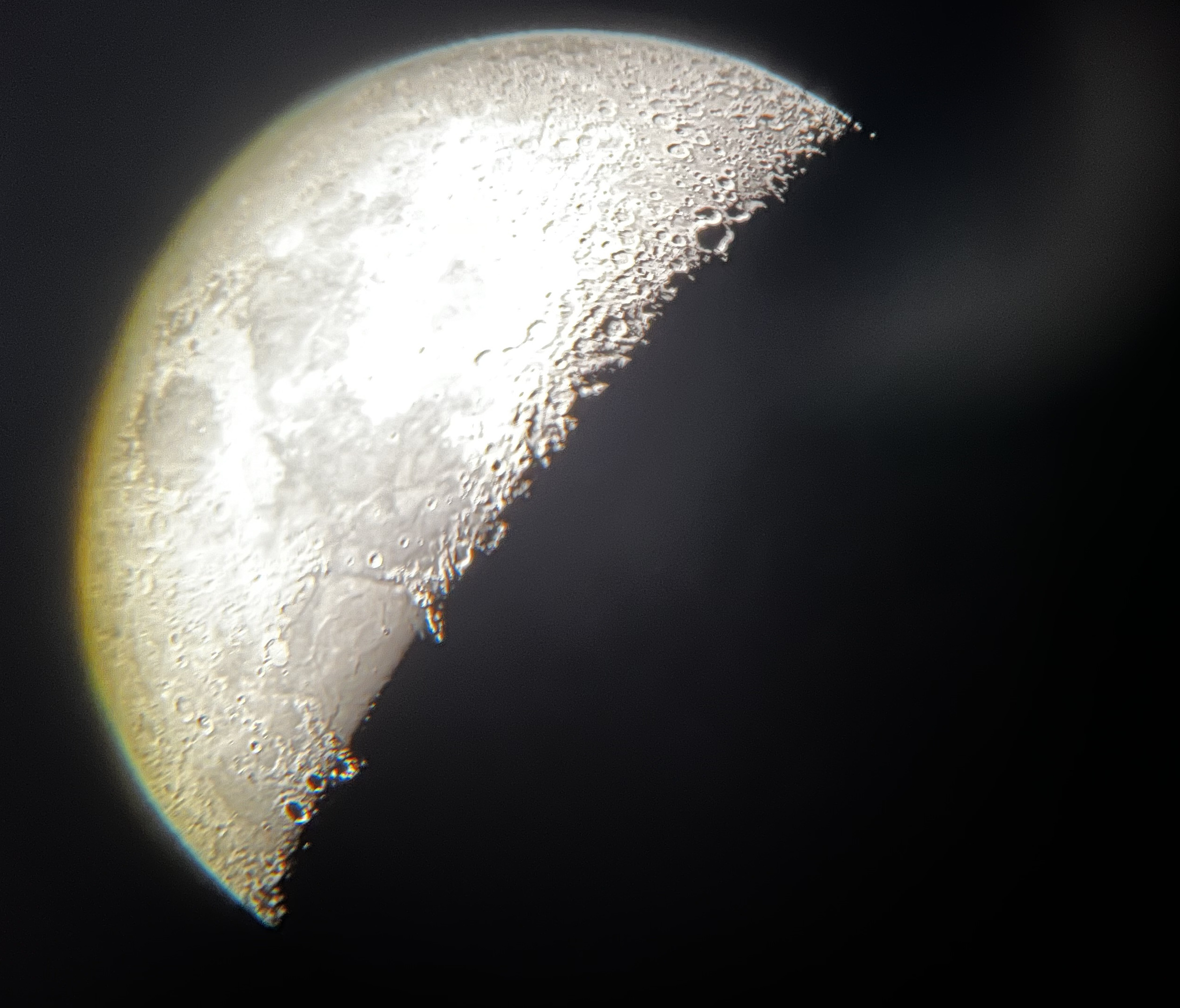
And, it works. I captured the following moon images by holding my iPhone 13 Mini camera up to the eyepiece. The focus is a bit wonky and you can see some chromatic aberration around the edges of the moon (the blue-ish lines), but all in all, I'm pretty impressed with the clarity of these pictures.
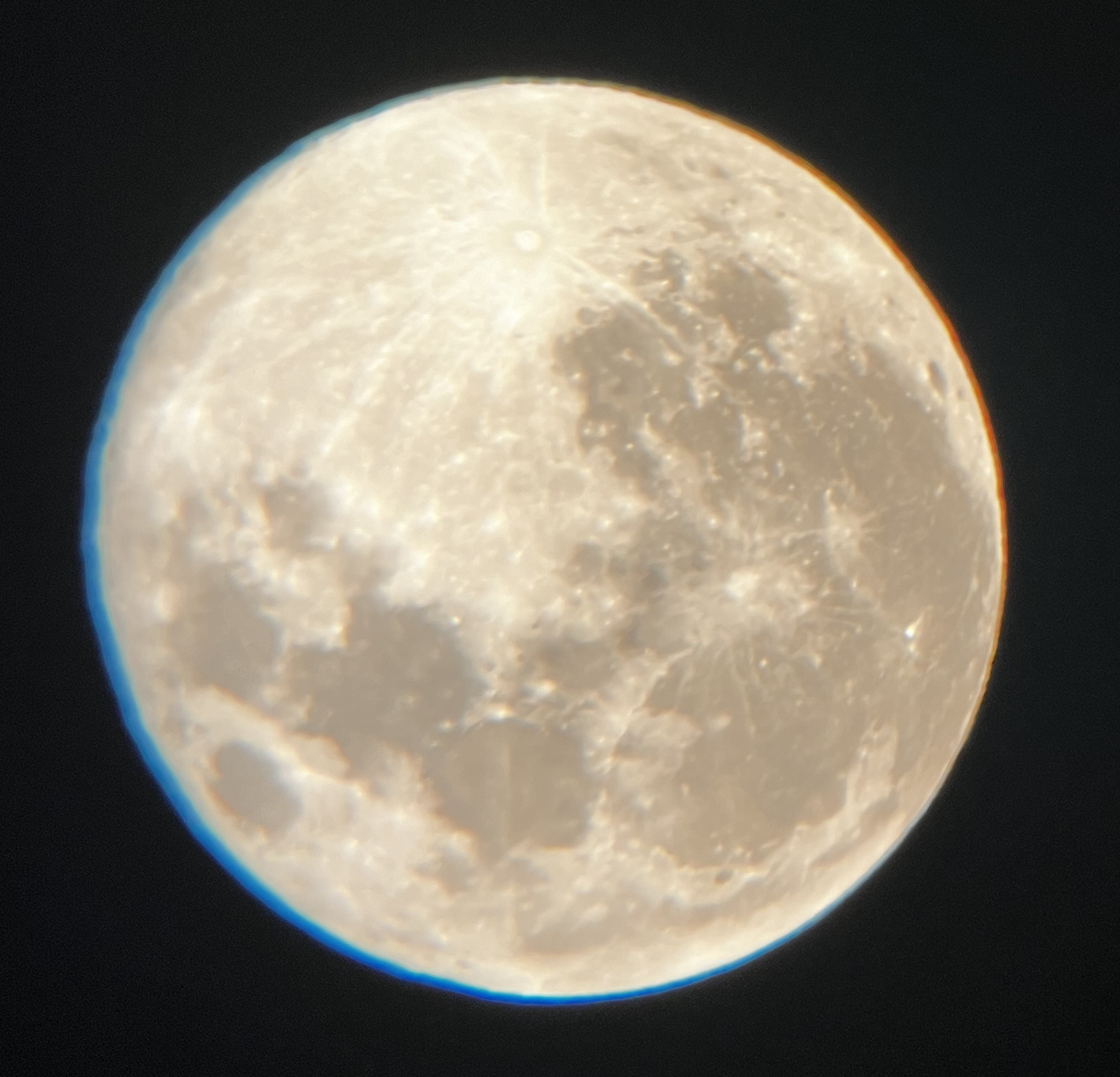
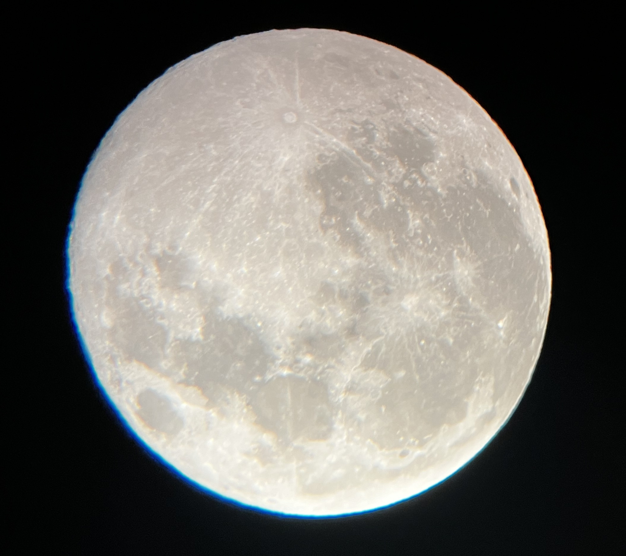
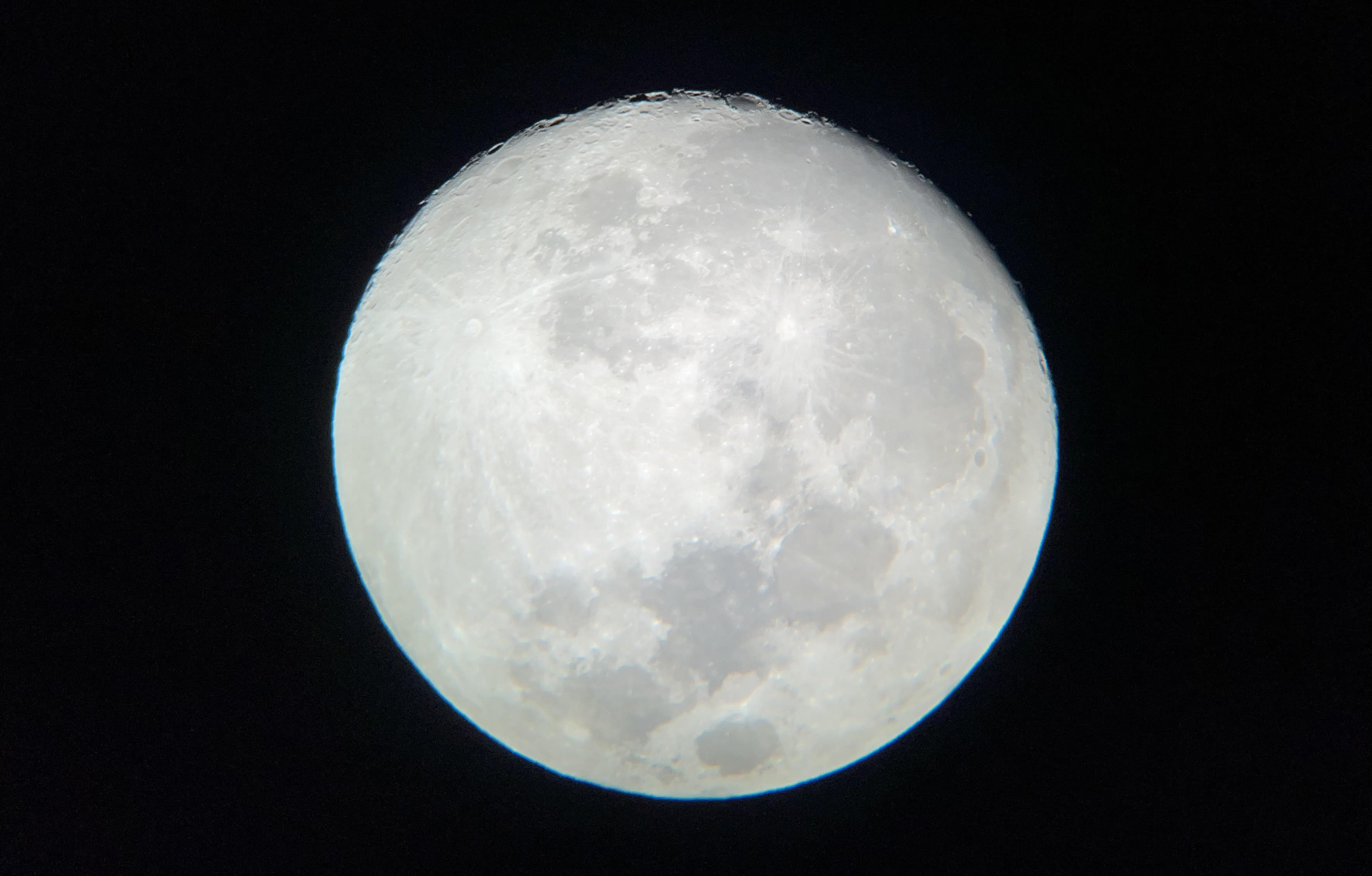
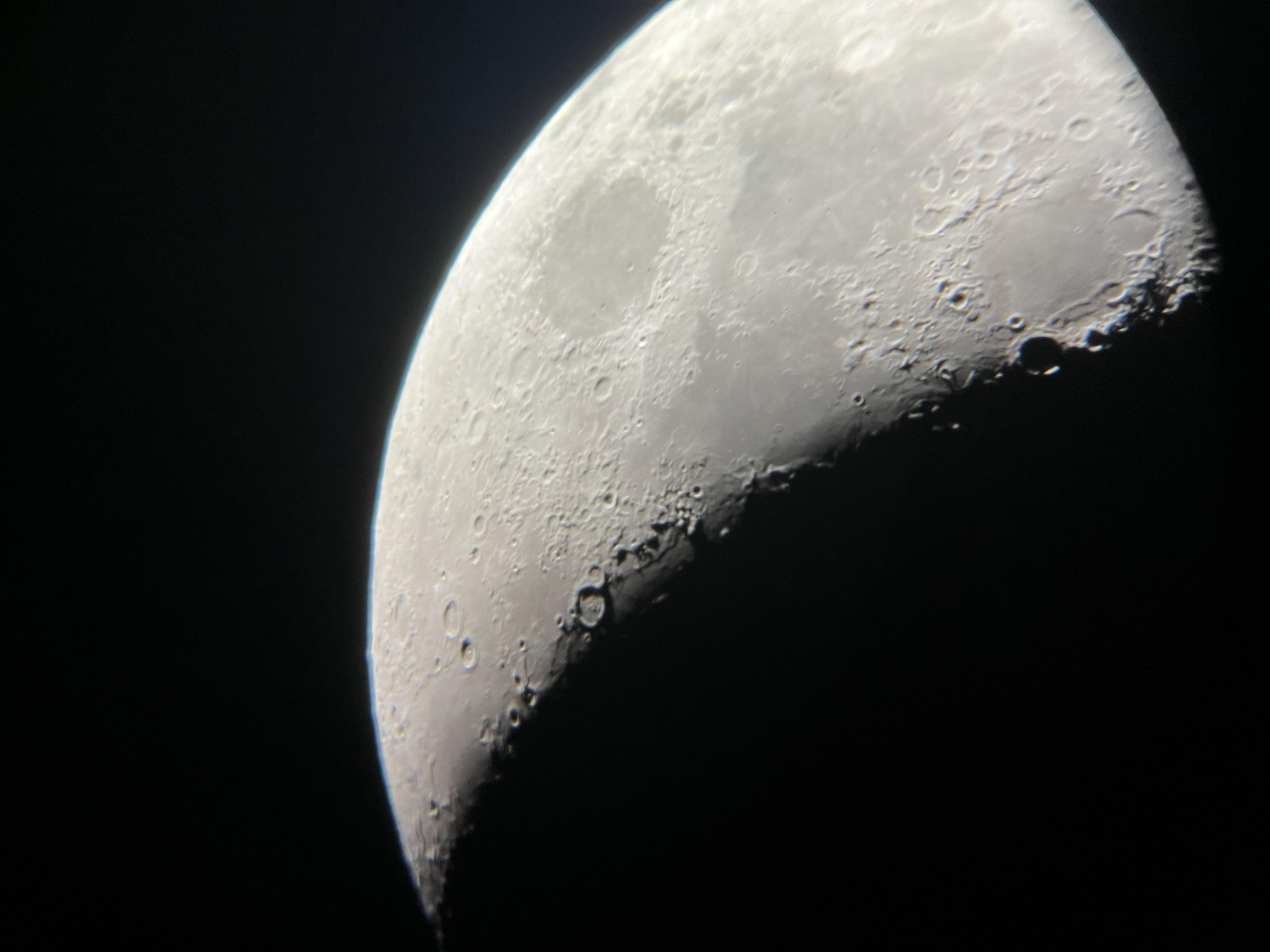
It's quite surreal, standing there, looking at such a high fidelity image of a rock hundreds of thousands of miles away. It almost doesn't seem real, like some sort of uncanny deception, and it certainly reminds you of how small you are.
Aside from the Earth's moon, I've been able to see Jupiter and its moons too. The image is clear enough to make out the prominent lines of Jupiter with the eye. Unfortunately, my iPhone camera doesn't seem capable of capturing a clear image. I also haven't taken the scope to a dark sky spot, so I haven't made an effort to view deep sky objects yet.
IV. Next steps
Astrophotography has been on my mind during this entire build. In order to capture images of deep sky objects, one needs a nice camera and a telescope with a tracking mount to account for the Earth's rotation. I have some ideas on how I can motorize the mount I've just created, but haven't got around to implementing them yet. I also have a salary and no dependents, so the camera is only a click away. Stay tuned...